Evolutionary Value Added Measurement System
In recent years the number of smart devices we use has increased significantly. The role of the analog / sensor IC has become critically important not only in the smart society but also in other fields. More than ever, higher performance, tighter accuracy and longer reliability are required for those devices. To address these challenges measurement systems need to have many features while maintaining a very low test cost and engineers tasked with developing test programs require very good coding skills plus in-depth operation knowledge of the test system.
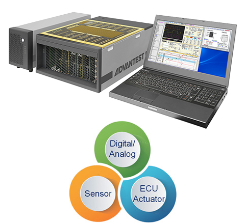
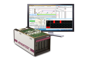
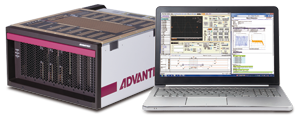
The new highly integrated measurement system "EVA100" is supporting Power Supplies, SMU( 4 quadrant DC Signal Measurement Units ), Pattern Generators, Arbitrary Waveform Generators, Digitizers and Oscilloscopes necessary for complete analog / mixed-signal / sensor / digital IC devices and Modules including Electronic Control Unit (ECU) for automotive evaluation and measurement.This new measurement system allows engineers quickly to build their own measurement environment without combining several standalone instruments.
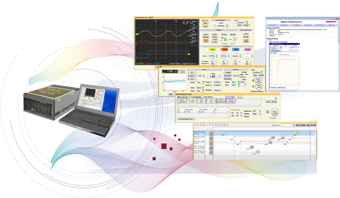
The EVA100 Software GUI is extremely intuitive, requiring only drag & drop operation, enabling engineers to create device focused measurement set ups in a very fast and simple manner. Automatic report functions dramatically improve the efficiency of deskwork, providing clear documentation and data ready for publishing in device data sheets.
Features
This new measurement system EVA100 that "Can do what you want, quickly" for the characterization, functional evaluation and mass production evaluations of low pin count analog(*1), mixed signal(*2) and Digital IC(*3) devices.
-
*1DC-DC Converter or Voltage regulator ICs
-
*2AD Converter DA Converter ICs
-
*3MCU or Standard Logic ICs, DFT Test
Small
All necessary functions are integrated into the compact body which has VI sources, Digital and Signal Capture.
Testing Units
Digital Unit: 220mm (W) × 472mm (D) × 206mm (H)
Analog Unit: 363mm (W) × 472mm (D) × 206mm (H)
High Performance
The Event Master Sequencer (EMS) controls the hardware with high timing accuracy and high precision enabling superior repeatability. Analog VI source, General Control Module and Signal Capture instruments provide versatile and comprehensive measurement capability.
Intuitive
No programming language environment offers very intuitive operation for users, so that everyone from the beginner to expert is able to use the system quickly. Automatic report generation tools reduce the need for additional deskwork, improving the efficiency of evaluation and measurement tasks dramatically.
Expandable
Stackable Testing Unit architecture supports many scenarios from design to production for analog and Mixed Signal devices.
Supporting external instruments, customized measurement
systems can also be created according to more specific requirements and needs.
Main Functions
- EMS (Event Master Sequencer)
- AVI (Analog VI source)
- MVI (Middle power VI source)
- HVI (Floating High Voltage VI source)
- SCAP (Signal CAPture module)
- GCM (General Control)
- LF (Low Frequency AWG/Digitizer)
- HF (High Frequency AWG/Digitizer)
- SYNC (Synchronization)
- DM64 (64ch Digital Module with Analog, Power Supply Function)
- Synchronized Sequence Control (Sequence Editor)
- Protocol Support (RegisterMap)
- Profiling the Execution Time (Profiler)
- Optimizing Test Flow (Optimizer)
- Test Specification Table (Test Condition Editor)
- Documentation (ReportGenerator)
EMS (Event Master Sequencer)
The EMS controlls the system bus and distributes the reference clocks.
-
Optical Connection to Controller (PC, EWS)
-
System Bus control and synchronization
-
Synchronization between EVA systems
-
Control of External Instruments (e.g. Measurement equipment or Thermal Streamer)
By adding a temperature sensor on a performance board (PB), evaluation activities under temperature test can be automated.
AVI (Analog VI source)
The AVI is a Source and Measurement Unit for supplying voltage and current to the device under test (DUT). Each channel can supply up to 500mA current and up to +/-64V. Arbitrary Waveform Generator and Digitizer capabilities per pin enable the simple creation of complex measurements.
MVI (Middle power VI source)
MVI has the same functionalities as AVI, supplying voltage and current to the device under test (DUT). Each channel can supply up to 2A DC current and a voltage range of +/-128V, suitable for higher power output DC-DC converter ICs.
HVI (Floating High Voltage VI source)
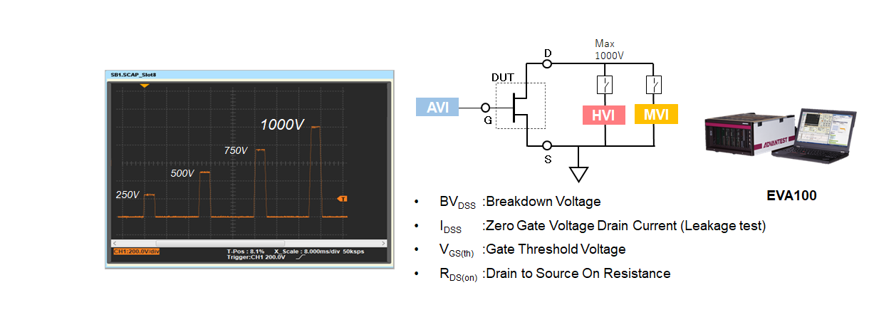
HVI is the Source and Measure Unit for leakage current and breakdown voltage tests. Up to 1000V voltage, Floating and Glitch-less mode switching capabilities provides powerful and fast measurement for AC-DC convertors or LED drivers such a high voltage devices.
SCAP (Signal CAPture module)
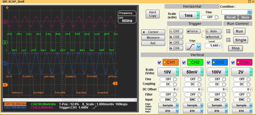
4 channels high frequency sampling digitizer to observe and measure the transient response waveform or behavior from device under test (DUT).
GCM (General Control Module)
Supports digital control with protocol based commands and the control of relays and external circuitry on the performance board (PB).

LF (Low Frequency AWG and Digitizer)
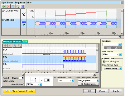
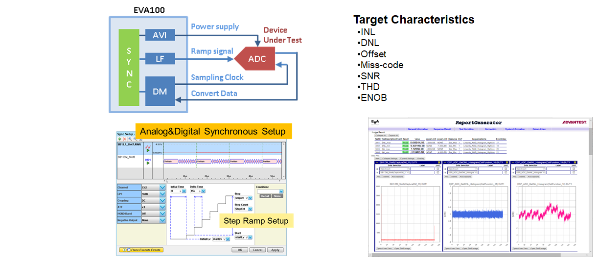
The LF is an arbitrary waveform generator and waveform digitizer module covering analog measurement up to the 200kHz band width. With low distortion and low noise characteristics, it is suitable for test and evaluation of high precision devices such as audio band devices or sensor devices. The Sync Setup fully synchronizes the LF and DM (digital) modules for precise linearity test of ADC devices.
HF (High Frequency AWG and Digitizer)
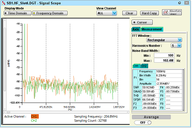
The HF is an arbitrary waveform generator and waveform digitizer module covering analog measurement up to the 200MHz band width. The HF module covers a wide range of analog devices from video band to baseband band devices. The function generator and FFT analysis tools make design evaluation very efficient and productive.

SYNC (Synchronization)
The SYNC controls the system bus and distributes the reference clocks, specially excellent Digital synchronization.
-
Optical Connection to Controller (PC, EWS)
-
System Bus control and synchronization
-
Synchronization between EVA systems
-
Utility Power Supply and Control of relays
-
Control of External Instruments (e.g. Measurement equipment or Thermal Streamer)
By adding a temperature sensor on a performance board (PB), evaluation activities under temperature test can be automated.
DM64 (64ch Digital Module with Analog, Power Supply Function)
Highly integrated measurement module such as Device Power Supply, Analog capability and Digital Pattern Generation. Matrix function allows simplified device interface design by routing the analog signal Input and Output path from Digital channel. Time Measurement Unit, VBump Function, Reference Voltage.
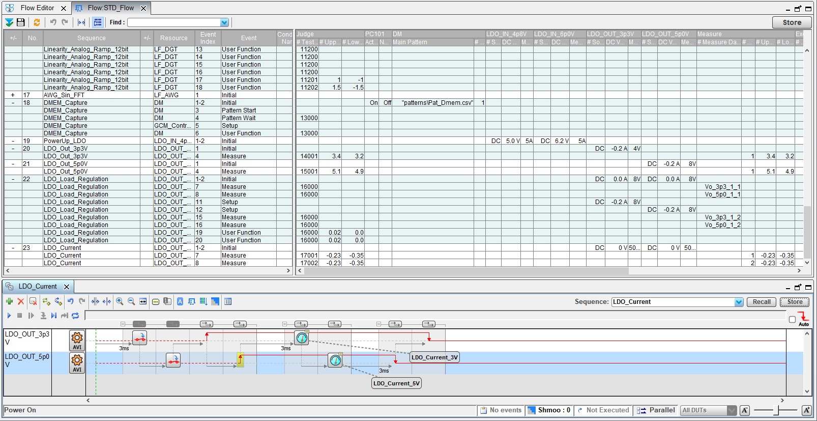
Synchronized Sequence Control (Sequence Editor)
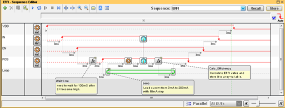
Sequence Editor makes it easy to synchronize multiple hardware channels based on how the user determines when events occur. The Sequence Editor also supports continuous measurement or conditional loop settings enabling greater control of automated measurements.
Protocol Support (RegisterMap)
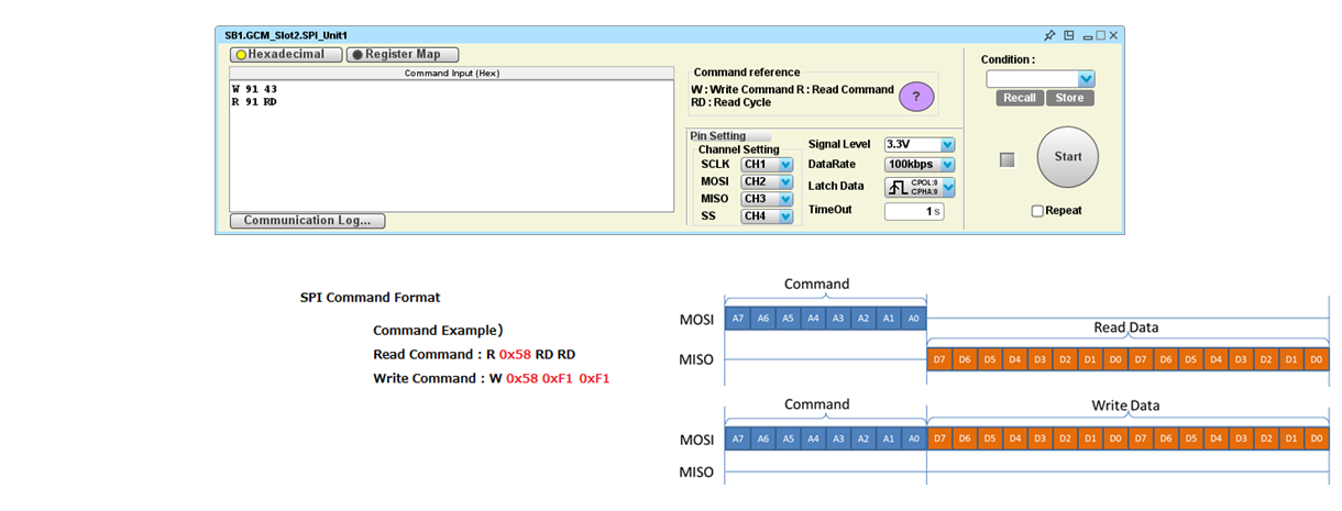
I2C, SPI, JTAG I/F are supported by protocol based control. By preparing the RegisterMap, We can use the register name for digital patterns instead of neumonics so that RegisterMap gives you the very clear overview for the digital pattern and improve readability and efficiency of digital pattern debug.

Profiling the Execution Time (Profiler)
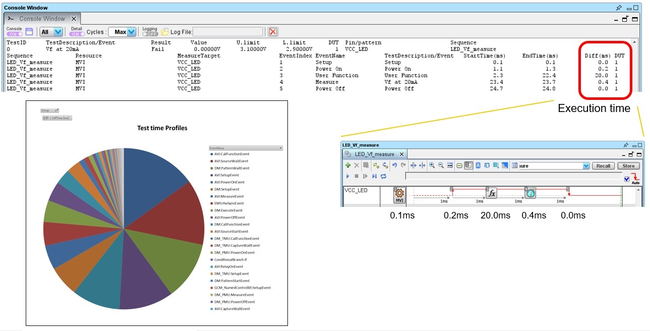
The Profiler measures the execution time of each event automatically. When the test time reduction (TTR) is needed, the detailed execution time (editable by a spreadsheet software) from the current sequence / flow can be collected by clicking the button. It provides the clear guideline for a task of TTR.
Optimizing Test Flow (Optimizer)
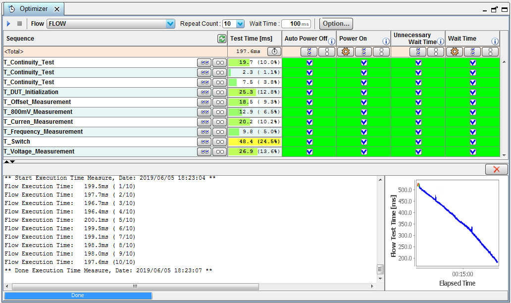
Wait time, relay control and power on/off control will be optimized. Without the deep knowledges and efforts by skilled engineer, the Optimizer helps to reduce the test time with keeping the test quality and results (monitoring statistical data). Support the best efficiency and productivity in a production.
Test Specification Table (Test Condition Editor)
Test Condition Editor displays the settings and conditions in sequences onto a table format. During the debugging, power supply voltages, forcing currents and limit values can be easily verified and helps to create documents (test report/condition table, etc.) after debugging.
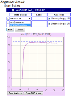
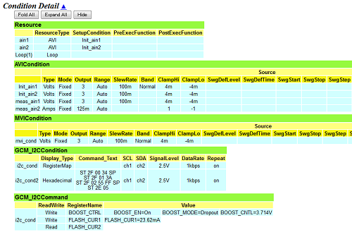
Documentation (ReportGenerator)
The Test Conditions and Results for each measurement is reported as a HTML format which can include graphical data. Automatic report generation frees users from taking notes each time during debug sessions and exporting data, with formats such as CSV, further analysis and documentation can be performed seamlessly.
Main Specifications
| Basic Operation Software | Microsoft Windows 10 Pro 64bit (English or Japanese) Microsoft Windows 10 Enterprise 2016 LTSB 64bit (English) Microsoft Windows 11 Pro 64bit (English or Japanese) Microsoft Windows 11 IoT Enterprise LTSC 2024 64bit (English) |
|---|---|
| Intuitive Software | No programming language environment |
| Support Protocol | I2C,SPI,JTAG are supported |
| Easiness and repeatability | Useful Sequence Gadgets (Templates) are available |
| Compact |
Digital Unit size : 220mm (W) × 472mm (D) × 206mm (H) weight : ~9kg (minimum configuration) Analog Unit size : 363mm (W) × 472mm (D) × 206mm (H) weight : ~11kg (minimum configuration) |
| Production capability | Stackable up to ×4 Testing Units |
Microsoft, Windows are either registered trademarks or trademarks of Microsoft Corporation in the United States and/or other countries.
Digital Unit
Synchronization
-
Synchronization among Modules and Units
-
Relay Control (64 user control bits)
-
Hardware synchronization
Device Power Supply
-
Voltage Range 7V Current Range 500mA
-
Parallel operation, IDDq Measurement, VBump function
Pattern Generator
-
100MHz Pattern Generator (64ch I/O), Maximum 1024 ch
-
Per Pin Parametric Measurement Unit (64ch)
-
Time Measurement Unit (8ch)
Arbitrary Waveform Generator and Digitizer
-
Arbitrary Waveform Generator (500ksps/18bit) (4port)
-
Digitizer (500ksps/18bit) (2port)
-
Reference Voltage Source (1ch)
Analog Unit
General Interface Controller
-
Up to 100Mbps Pattern Generator (8ch)
-
Protocol support for I2C, SPI, JTAG
-
Relay Control (64 user control bits)
-
Hardware synchronization
Analog VI Source
-
Voltage Range +-128V Current Range +-2.0A (DC) / 5.0A (Pulse)
-
Voltage Range +-64V Current Range +-500mA (DC)
-
Voltage Range 1000V Current Range +-10mA (DC) / 20mA (Pulse)
-
Arbitrary waveform generator, Digitizer, Differential Volts meter
Pattern Generator
-
Up to 100Mbps Pattern Generator (32ch I/O)
-
Low Jitter Pin (8ch I/O) / Low Jitter Clock (1ch)
-
Per Pin Parametric Measurement Unit (32ch)
-
Time Measurement Unit (4ch)
Precision Arbitrary Waveform Generator and Digitizer
-
Arbitrary Waveform Generator (200ksps/24bit 80kHz BW) (Differential 4ch)
-
Digitizer (625ksps/24bit 200kHz BW) (Differential 4ch)
-
Per Pin Parametric Measurement Unit (16ch)
High Speed Arbitrary Waveform Generator and Digitizer
-
Arbitrary Waveform Generator (512Msps/16bit 200MHz BW) (Differential 2ch)
-
Digitizer (250Msps/16bit 200MHz BW) (Differential 2ch)
-
Per Pin Parametric Measurement Unit (8ch)
Signal Capture
-
1Gbps (max. 2Gbps) Sampling (4ch)
Application and Solution samples
Application
Solution
Measurement Items, Devices
I2C/SPI Communication
Support Digital Control
SCAN
Support a huge SCAN Pattern

IDDQ
Pattern controlled stand-by current measurement

VBUMP
Pattern controlled device power supply voltages

Trimming
Digital Trimming

DC-DC Converter
Characterization analog parameters i.e.) EFFI

AD Converter/DA Converter
High resolution converter evaluation
MosFET/IGBT
High Voltage leakage measurement
Please contact us from inquiry form for more details.
Tools, Options, Expansion
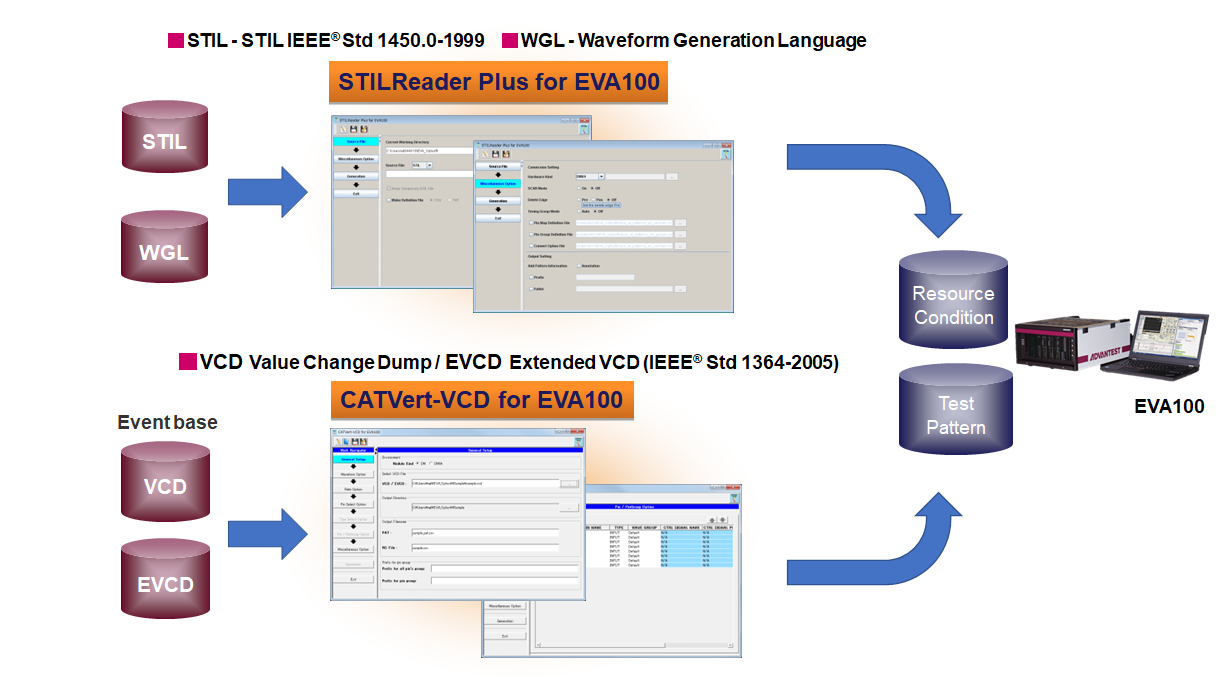
EDA Link tools
Pattern Generation from STIL/WGL/VCD format
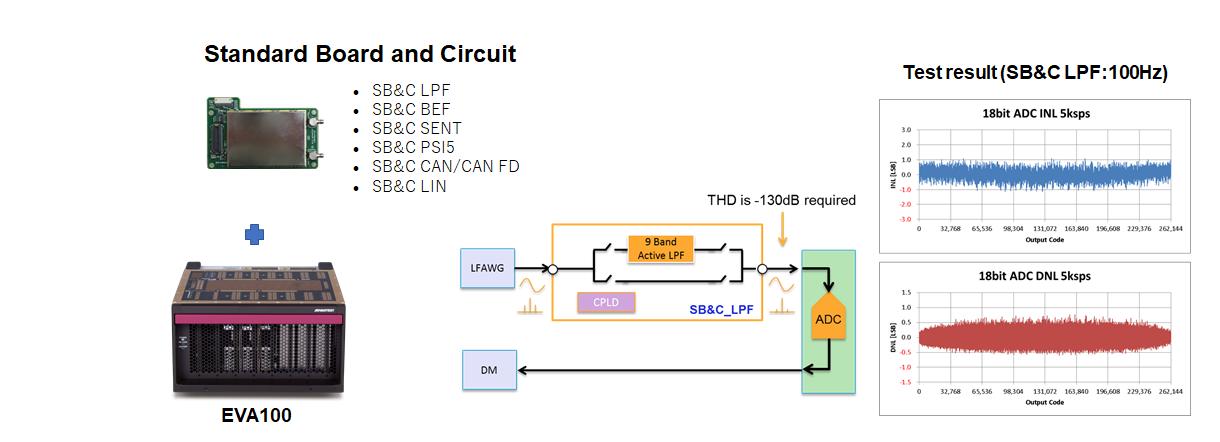
Option Hardware
Support various interfaces and extension of hardware
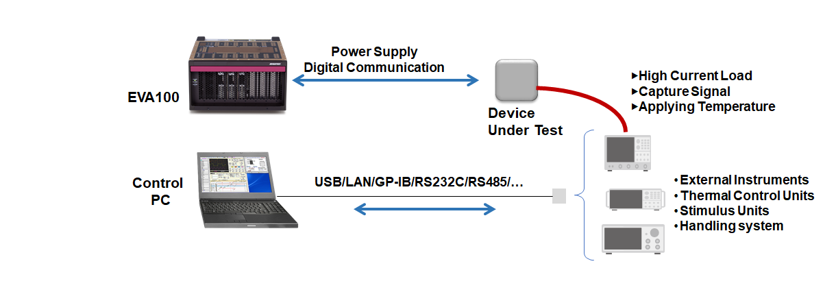
Control external instruments
Integrate a thermal control unit, Oscilloscope and other instruments to EVA100
Please contact us from inquiry form for more details.
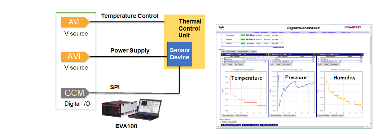
Sensor Solution
Atmosphere pressure, temperature, humidity Sensor (SPI/I2C)
Validation and measurement for each sensor
Angle Sensor (SENT Protocol)
Support special protocols

Test Cell Solution
Combine Pressure and Magnetic injection unit

Sensor ASIC Test Solution
ALL-In-One system for ASIC characterization

Please contact us from inquiry form for more details.
ECU Test Solution
Evaluation of ECU/Actuator
Motor control ECU

Setup communication protocol
Easy setup CAN Data from ".dbc File"

Automatic switch control and operation
Easy operation and improve test accuracy
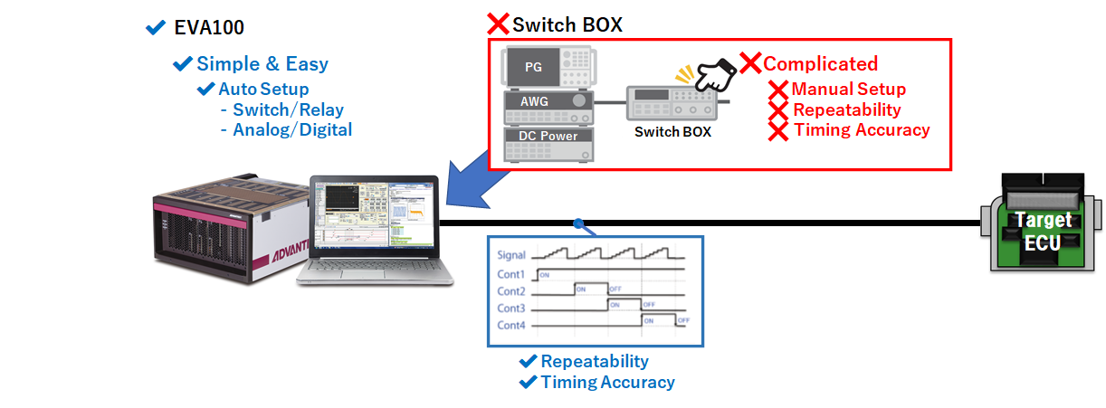
Evaluation of various actuators
Measure & Judge Electronic Water pump

Please contact us from inquiry form for more details.
Production Solution
Launching Production Line
Support a production line launch connection to handling equipment.
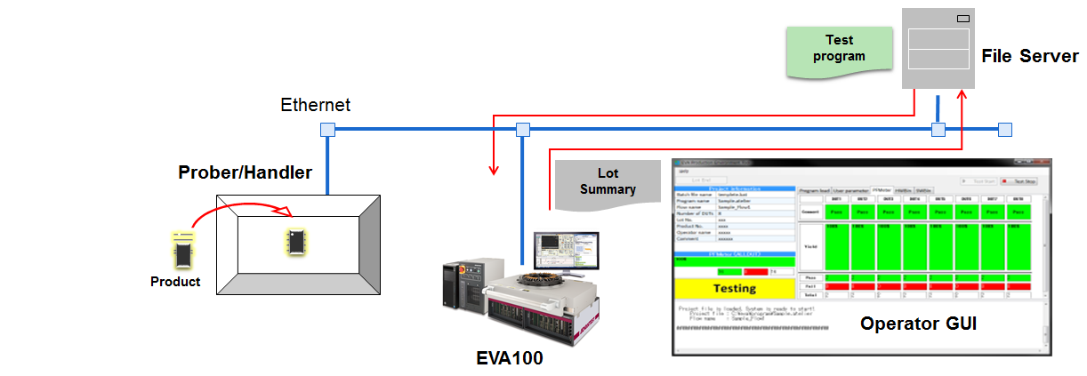
Shorten TAT from design through production
After evaluation, start the production immediately.
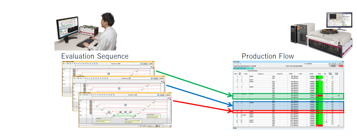
Please contact us from inquiry form for more details.
Faliure Analysis Solution
Connecting Emission microscope
Small footprint, easy operation provide efficient evaluation system
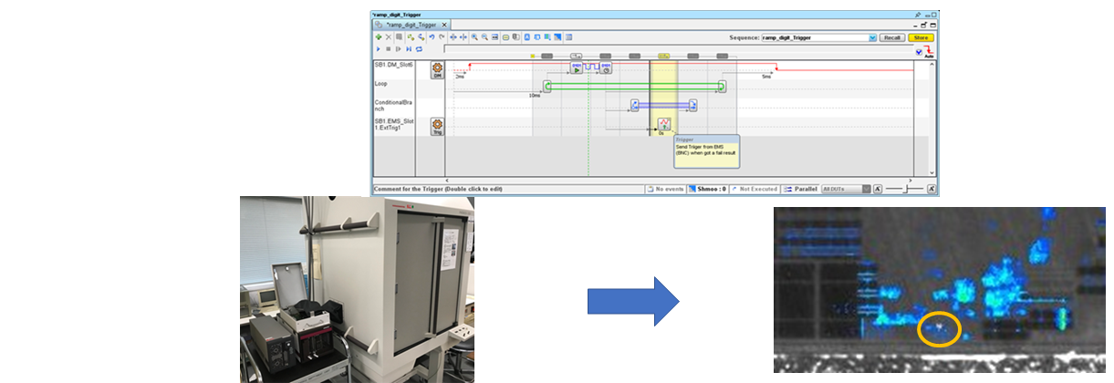
Failure detection Solution
Realize defect chip analysis in graphical interface

Frequently Asked Questions
For valuable EVA100 customers (login required)General Questions for EVA100
-
QHow can I get a user account?
AYou can register your account as follows.
-
1.Go to 'Customer Service' on our website and then to the 'MyAdvantest' page.
-
2.Click 'New User' on the login dialog.
-
3.Fill in necessary information and click "Register".
-
4.Confirmation e-mail will be sent to the registered e-mail address. Click on "Confirm E-Mail".
-
-
QWhat's the EVA100?
AEVA100 (E-Model) is the system for engineering usage. E-Model connects to a laptop PC and customer projects like evaluation/characterization/debugging of analog, mixed signal ICs or modules are easily completed.
-
QWhat are the benefits of EVA100?
ACompact, Automation and Repeatability, Short Development Time, Easy and Intuitive Software
-
integrates VI Source, Waveform Capture functions and Device Control function into a single compact frame.
-
Measurements and evaluations can be made with intuitive operations without the need for programming language.
The Generate Report function can dramatically increase the efficiency of tasks like data tables and figures. -
The expandable architecture and software environment can be applied to all kinds of processes from design and evaluation to mass production and product selection. A customized, evaluation environment can be achieved by connecting EVA100 to external measurement instruments through GPIB I/F.
-
-
QDo I need to prepare any peripherals for the EVA100?
AE-Model: customers will need to prepare PC, PCIe adapter and cables.
P-Model: customers does not need to prepare any peripherals except optional parts. -
QI would like to try EVA100. Is there any demo system available?
AYes, we can do the online demonstration and a free trial on a demo system is available.
Please contact us for more details. -
QIs there a system for Production model?
AWe have P-Model for Production.
The P-Model docks to an automatic handling system (a handler or prober) using TTL/GP-IB for testing the devices in a factory. -
QCan I use EVA100 for mass production?
AThe P-Model is the mass production model of the EVA100 system. After evaluating devices with the E-Model, customers can immediately start production with the P-Model. Total development time (from design to production) can be shortened dramatically.
-
QWhat's the difference between E-Model and P-Model?
AMaximum Number of SBs (Shoe Box) is increased to support multiple DUTS plus SEMI Safety standard are implemented on P-Model.
-
QIs there any training class?
AWe have no pre-planned training course, however we can offer you training class at your request.
-
QWe would like to ask for the application development, Is there any company we can ask?
APlease contact us, we are willing to introduce you our partnership company.
System
-
QWhat is the recommended PC Specification?
AHere is the required PC specification for E-Model (engineering).
CPU: >2.2GHz, 4core
Memory: > 8GB
HDD/SSD: > 128GB
Display resolution: > 1366×768
I/O: ExpressCard×1 (mandatory I/F)
USB2.0×2, Ethernet×1 -
QCan we use a desktop PC for E-Model?
AYes, PCIe Host adapter "PCIe-8361" is required for PCI slot.
-
QWhat kind of configuration are available?
AThere are several configurations each optimized for different applications or products.
Please contact us for more details. -
QHow noisy is the fan?
AThe noise level is less than 60dB.
-
QAre there any accessories?
AYes, we have several accessories for high accuracy measurements and also connection kit for easy access to the evaluation board. Please contact us for more details.
-
QWhat kind of power supply is needed?
AE-Model: Single-phase AC power supply. Input range is 100V~240V, 50/60 Hz. The system supports automatic switching between 100 VAC and 220 VAC systems.
P-Model: Single-phase AC 200V power supply. Input range is 200V~240V, 50/60 Hz. -
QHow often do I need system calibration?
AThe accuracy of internal standards is guaranteed for one year after calibration.
In order to maintain the system accuracy, we recommend that the internal standards be calibrated every year. -
QCan the system operate modules in synchronization?
AWith the Hardware Sync function, customers can operate modules synchronously.
Please refer to the EVA100_GUI_Reference_Manual for details. -
QWhen should the AVI Stack Mode be used?
AThe AVI's VS (Voltage Source) mode enables voltage-added output by connecting voltages of multiple channels in series. This mode can be used when the applied voltage is not enough with single channel. For example, this mode is suitable for evaluating and producing multicell battery monitoring ICs.
-
QWhat is the pulse generation width of the MVI Module?
AThe pulse generation width of the MVI module is limited by current usage.
For more details, refer to performance specifications. -
QHow do you use Control Bits?
AControl Bits have 64 bits and can be used to control relays etc. on a PB. For the control method, please refer to the EVA100_GUI_Reference_Manual. The PB Design Guide explains how to connect control bits.
-
QCan the EVA100 be used for direct control of a 12V relay?
ASince the resistance of the control bits is only 5V, it does not allow direct control of a 12V relay.
Please use the relay drive power supply (12V / 1A) on the PB. -
QCan the LF Module be used as a single end?
AYes, in between Posi-PosiGnd and Nega-NegaGnd.
Please refer to the PB Design Guide for recommended circuits. -
QWhat are the specifications of the SB&C for the LF Module?
APlease see the Standard Board and Circuit column in the Downloads section of the Advantest's website EVA100 product page.
-
QWhat is the DM Module's low jitter pin 1-5-9-13-17-21-25-29 used for?
AThese pins have less jitter compared to other pins. Please use it according to the required performance.
For more details, refer to performance specifications. -
QCan we use some instruments with EVA100?
AYes, it is possible.
The instruments need to have GPIB, USB or LAN interfaces. -
QHow does EVA100 connect with external Instruments?
AIn case of GPIB, we use NI GPIB-USB Controller to connect between control PC and external instruments.
The instruments are controlled through EVA100 Software.
If external instruments support USB interface, User can control it by User Function.
Software
-
QDo you support Windows 11?
AYes. Microsoft Windows 11 Pro 64bit is supported after Measurement Atelier R2.70.
-
QHow to get the Windows OS?
AP-Model includes the EWS with preinstalled Windows OS.
E-Model needs the preparation for PC which installed Windows 10 Pro 64bit or Windows 11 Pro 64bit. -
QDo I need to buy the software in addition?
ANo. Software is included in the system.
What are prerequisites for the laptop computer?
Windows 10 Pro 64bit or Windows 11 Pro 64bit and Java Development Kit 64bit Version 8 are required. -
QWhich version of Java does the system require?
ALess than R1.20: JDK (Java Development Kit) 7. R1.20 and above: JDK 8.
-
QWhat programming language is used for test program?
AA programming language is not mandatory for the Test Sequence development, it can be easily built by deploying several event icons on the GUI.
-
QDo project files created with different Measurement Atelier revisions work?
AProject files created with the old revision Measurement Atelier can be used with the new revision Measurement Atelier, but not the other way round.
-
QCan I load a project file from batch files?
AYes, with ateliercmd. For details, refer to "Loading Project File (-load)" in the GUI Reference Manual.
-
QHow can I change module configurations in Atelier Editor?
AEdit "% USERPROFILE%\MeasurementAtelier\SystemConfig\SystemConfig.csv".
For details, refer to "Setting the system configuration" in the GUI Reference Manual. -
QCan I do the Go/No-Go test?
AYes, You can set limit values for each measurement, if the measured value is out of range or not.
-
QHow to add my own calculation?
AYou use the FUNC(user function) or SET VARIABLE on the sequence.
Please refer to “SET VARIABLE” of the EVA100 GUI reference manual for the details of the SET VARIABLE event.
Please refer to “EVA100 user function design guide” for user function.
For example, we recommend that you have the function the operation of array variables, the operation of analog properties (i.e. THD, SNR, EFFI etc.) -
QHow to save the measurement result?
AJudged values are displayed in the console window and you can save them as a test file. In addition, measurement results and details of test sequence (conditions, sequence) and system information can be stored as a report file.
-
QHow can I set a loop inside a sequence?
APlease refer to "Setting the loop" in the GUI Reference Manual.
-
QIs there a Measurement Atelier that does not require an actual system?
AThe "EVA 100 Atelier Editor" can be used without actual equipment. Please purchase separately.
-
QHow can I make a user function?
APlease refer to "Creating User Function" in the EVA100 User Function Design Guide.
-
QIs there any sample code of Java?
AYes, Click here for Java code reference. (Login required)
-
QCan we call the external DLL?
AYes. Refer to "Calling DLL" in the EVA 100 User Function Design Guide.
-
QHow do I access external files with user functions?
APlease refer to "File output" in the EVA 100 User Function Design Guide.
-
QWhere are the source files for user functions?
AFor those functions that are published, they can be downloaded from the Advantest website.
-
QWhat kind of information can DM capture?
AIt can capture pass / fail, fail count, etc. for each cycle.
For details, refer to Output file format (4), (5), (6) in the GUI Reference Manual. -
QCan STIL/WGL files be converted to EVA100 pattern files?
AYes, the optional software 「STIL Reader Plus for EVA100」 support the conversion.
-
QWhat kind of file format is a waveform(AWG)?
APlease refer to the "Waveform definition file" in the GUI Reference Manual.
-
QIf the path name of the project file contains "#", it cannot be saved?
ACorrect. Please use path names that do not contain "#".
-
QHow to install the OpenJDK?
APlease refer to the "Software installation manual".
-
QHow to find the Mac Address of the computer for license request?
AOpen the command prompt window then type the following command.
>getmac /nh
You can use the mac address at the first line.
-
QThe service option for [ATFLEX Server R1.00] is "AUTO(delay start)" by default. Is it OK to change to "AUTO"?
ANormally there is no issue, however rarely under the high loading status the server PC the license server program may fail to initially start. In this case please start it manually.
Please refer to the "ATLEX Package Installation manual" for how to start. -
QEncountered the error message "Cannot connect to license server system, ... (Error Code:001-999-009)" during option software start up.
AThe following possible causes:
-
1.No access to the license server machine or license server service is not running.
Confirm the network connection.
Confirm the ATFLEX license server service status. -
2.Reached the maximum license count or license has been expired.
-
3.Not registered the license file.
Register the license file you purchased.
Please refer to the "ATLEX Package Installation manual"
-
Product Catalog
| Title | Size |
|---|---|
| 2.08 MB | |
| 2.27 MB |
Technical Leaflet
| Title | Size |
|---|---|
| 1.87 MB | |
| 2.23 MB | |
| 1.16 MB | |
| 1.53 MB | |
| 788 KB | |
| 1.86 MB | |
| 1.44 MB | |
| 2.35 MB | |
| 1.74 MB | |
| 1.92 MB | |
| 2.30 MB | |
| 665 KB | |
| 770 KB | |
| 348 KB | |
| 442 KB | |
| 442 KB | |
| 500 KB |
-
EVA100